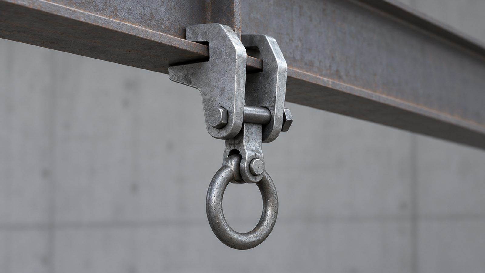
An anchorage connector is the hardware that couples a fall protection system to the structure, and in the United States it is governed as a product by ANSI/ASSP Z359.18-2017 — not by OSHA, which regulates the anchorage instead. Z359.18 defines three types: Type A for general active fall protection, Type T for a suspended component or tie-back line, and Type D, which may deform to absorb fall energy and so reduce the demand on the structure behind it. Type A and Type T must sustain a static load of at least 5,000 lbf (22.2 kN); Type D is qualified between roughly 2,700 and 5,000 lbf. There is no Type B or Type C. The whole category is forged, cast and machined metal, one of the purest fits for a precision metal manufacturer in PPE.
What is an anchorage connector, and what are the main families?
The anchorage is the structure — an I-beam, a purlin, a slab, a roof panel. The anchorage connector is the manufactured part that couples a lanyard or lifeline to it.
- Beam clamps and trolleys. Jaws gripping a beam flange; a clamp is fixed once set, a trolley rolls so the worker moves without re-anchoring.
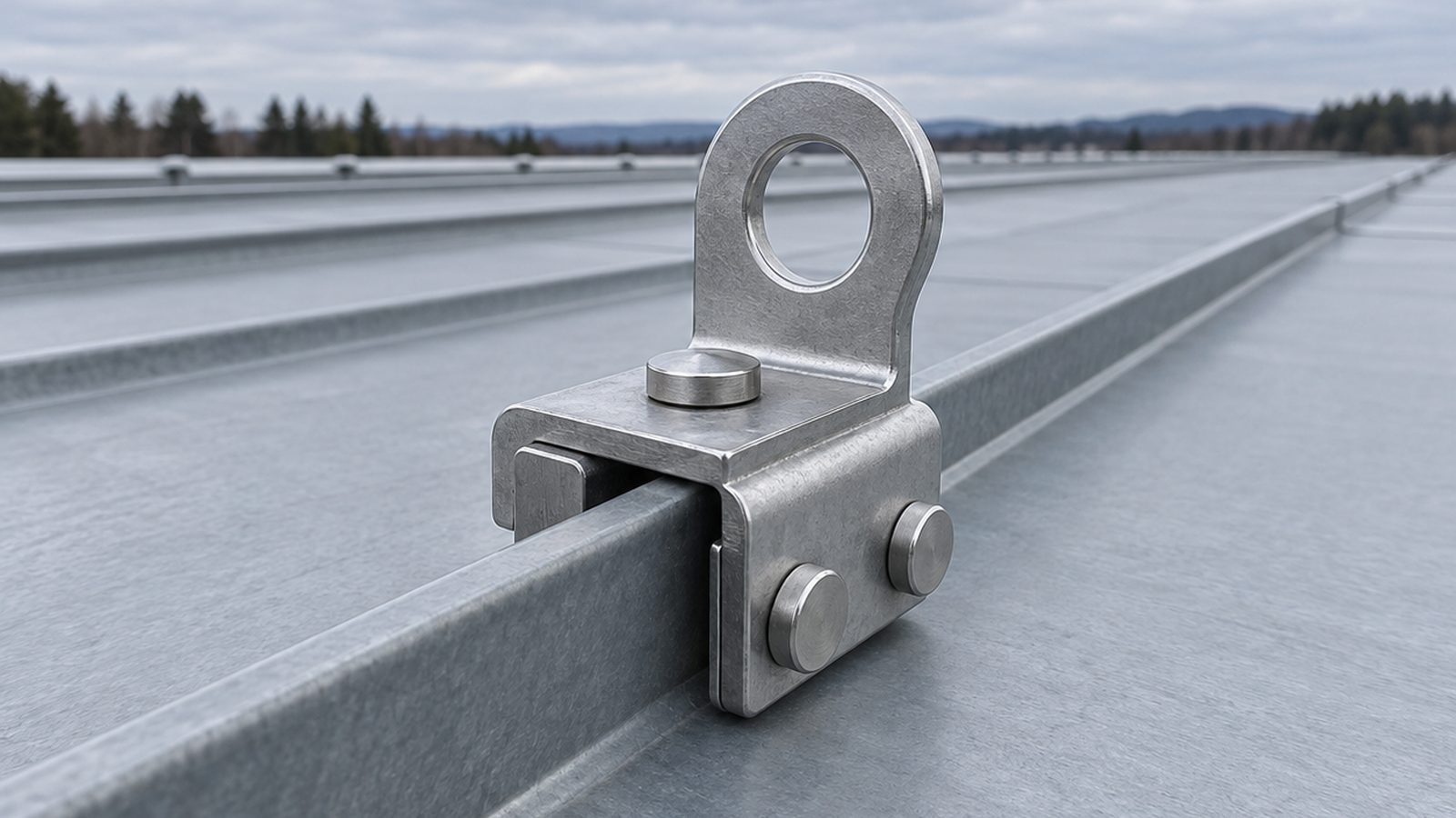
- Roof and standing-seam anchors. Clamps gripping a raised seam without penetrating the roof, plus plates and posts fixed through the deck.
- Concrete anchors. Cast-in inserts placed before the pour, and post-installed mechanical or adhesive anchors, reusable or single-use.
- Cross-arm straps and tie-off adaptors. Slings with a forged or stamped D-ring at each end, wrapped around a column or cross-arm.
- Permanent engineered anchors. Posts, davit bases and roof anchors specified by an engineer and left in place.
Horizontal and vertical lifelines are a separate family with their own standards; our lifeline systems guide covers those.
Which standard applies — ANSI/ASSP Z359.18 or OSHA?
Both, on different objects. OSHA 29 CFR 1926.502(d)(15) in construction and 1910.140(c)(13) in general industry govern the anchorage: it must support at least 5,000 lbf per attached worker, or be designed, installed and used under a qualified person’s supervision at a safety factor of at least two against the maximum arresting force. OSHA publishes no product standard for the connector itself. Z359.18 fills that gap from the manufacturer’s side; ANSI Z359.2 mirrors the OSHA logic on the structure side. A companion article in this series covers OSHA versus ANSI in full. A Z359.18 connector does not make a weak beam compliant, and a strong beam does not excuse an untested connector.
How are beam clamps and beam trolleys actually made?
The jaw body decides the product. It is hot forged in carbon or low-alloy steel, or investment cast where the geometry is too involved to forge economically, then quenched, tempered and machined at the load-bearing features. Forging wins on the hook profile because grain flow follows the curve instead of being cut across it.
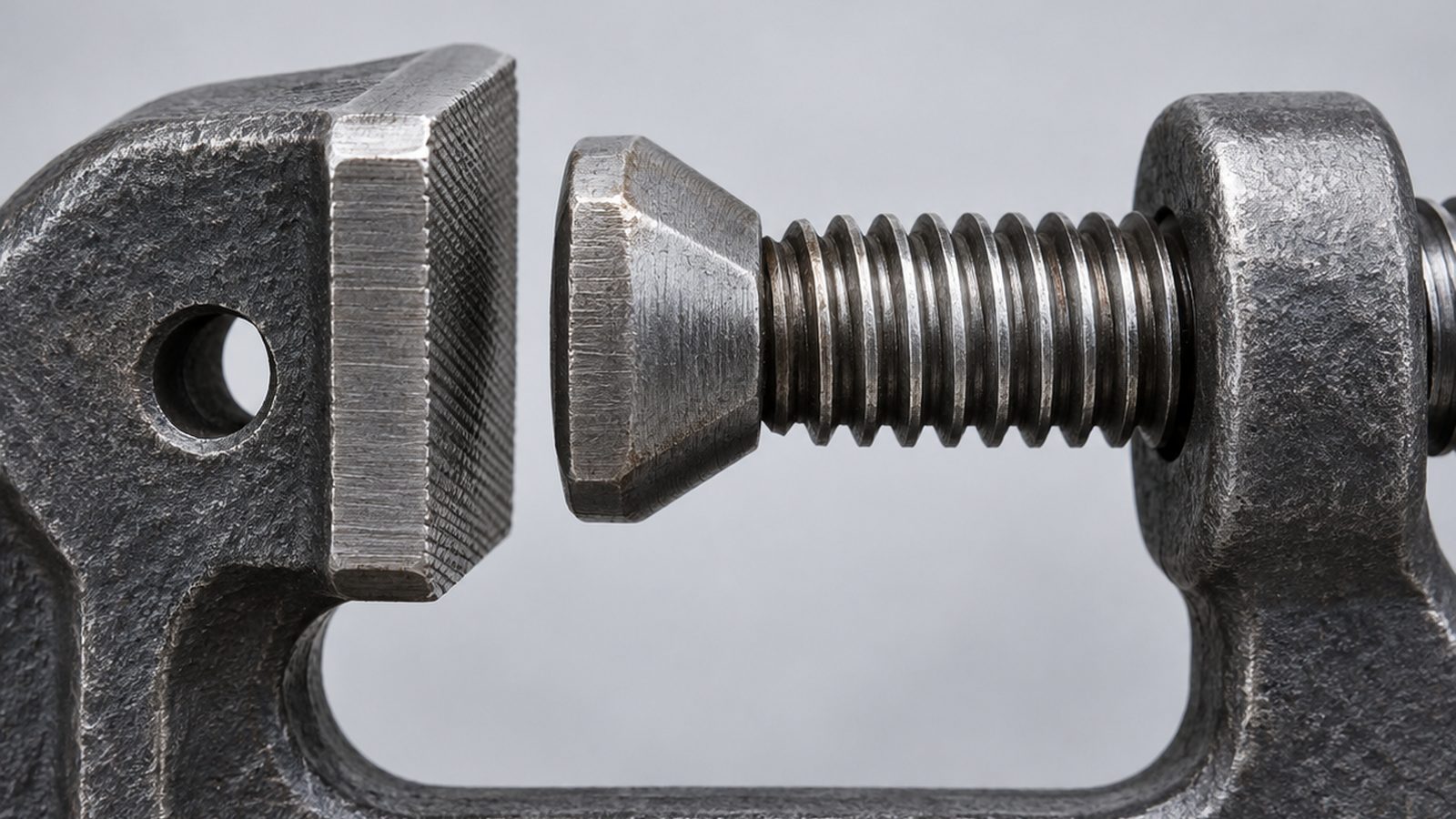
- The adjustment screw. A trapezoidal or ACME thread beats a V-thread: more flank area for the preload, a shallow lead angle that resists backing off. And the screw should set the grip, not carry the arrest load — the jaws must capture the flange, so a loosened screw still leaves a clamp that cannot pull off.
- The load-bearing pin. Loaded in shear, best designed in double shear. Material, heat treatment and bearing stress in the hole all need calling out.
- Wheels and bearings. Sealed ball bearings, with a wheel profile matched to the flange: wide-flange sections are near parallel while older S-beams taper.
Range is the problem underneath all three: the jaw contact angle changes as the screw travels, so a clamp spanning three- to ten-inch flanges meets its worst case at one end of that range, not the middle.
What makes a roof or standing-seam anchor hard to build?
It must hold 5,000 lbf without breaching the weathertight envelope or stopping the panel moving as it heats and cools. That rules out fastening through the panel and puts the whole load into friction and interlock on a thin folded seam.
Set screws do the clamping, and their point geometry is the quiet failure mode. A cup point bites through a panel’s metallic coating and leaves bare steel exactly where water collects; round-point and nylon-tipped screws exist to avoid that. Installation torque is panel-specific, which is why Z359.18 pushes manufacturers to assess every compatible substrate and fastener rather than publish one number.
Material pairing is the other trap. A stainless set screw on an aluminium or zinc-coated seam is a galvanic couple: small cathode, large anode, the favourable arrangement — reverse that ratio and the roof corrodes at the anchor.
Cast-in or post-installed: what governs a concrete anchor?
A cast-in anchor is a threaded sleeve set in the formwork before the pour; a removable eye screws in when needed. A post-installed anchor is drilled in later, mechanically expanded or set in adhesive. What decides whether it holds belongs to the site: embedment depth, edge distance, concrete strength, and whether an adhesive anchor’s hole was cleaned — drilling dust is the commonest cause of adhesive failure. Anchorage into concrete is a calculation under the concrete design code, ACI 318 Chapter 17, not a number a supplier assigns.
What actually gets tested, and what gets proof-loaded?
Z359.18 qualification is largely destructive, so it runs on samples. A Type A or Type T connector faces a static strength test to at least 5,000 lbf; a dynamic drop test with a 282 lb mass falling three feet, six for Type D, in which the mass must not reach the ground; a residual strength test reloading the same specimen afterwards; a serviceability test at working load; and salt-spray exposure whose duration varies by type.
Production testing is a separate decision. An anchorage connector is a single non-redundant load path, so many programmes proof-load every finished unit rather than sampling by lot — OSHA sets that precedent elsewhere, requiring D-rings and snaphooks to be proof-tested to 3,600 lbf without cracking, breaking or permanent deformation. But 100 percent proof loading is not a Z359.18 requirement, and a proof load set too near yield damages the part it is meant to prove.
Marking is a requirement in its own right: a permanently affixed label built to last the connector’s lifetime, carrying the standard number and type, any restriction on loading direction, the working load where specified, the minimum breaking strength, and a serial or lot number giving traceability. That last item keeps a recall bounded.
Why corrosion is a structural problem, not a cosmetic one
A permanent roof anchor is installed once and left exposed for a decade. Finish is therefore a strength decision: section loss at a jaw root, or a seized adjustment screw, is lost function long before anything looks dramatic.
Hot-dip galvanising gives a thick sacrificial zinc layer but plays badly with threads and close-fitting moving parts. Stainless in 304 or 316 earns its cost in coastal service while staying vulnerable to crevice corrosion in jaw and screw interfaces. Salt-spray hours to ASTM B117 or ISO 9227 belong on the drawing, though salt spray is a comparative screen, not a service-life prediction.
What belongs in an anchorage connector specification
- Rated capacity and direction. The Z359.18 type, the rated load, and any restriction on off-axis loading. A number without a direction is not a specification.
- Fit range. Flange width and thickness, seam profile and panel gauge, or hole diameter and embedment — naming the extremes.
- Material and condition. Alloy, heat treatment condition and hardness for every load-bearing part, with mill test certificates.
- Finish and pairing. Coating type and thickness, salt-spray hours, and fastener material chosen against body and substrate.
- Proof-load regime. Qualification tests and sample rate, and whether production units are proof-loaded 100 percent or sampled by lot, with load and hold time.
- Marking and traceability. Content, method, location, durability, and the lot scheme tying a unit back to its heat.
- Documentation. Test reports, material certificates, installation and inspection instructions, and the drawing revision each was run against.
Three further pieces in this series bear on the same decision: tool tethering under ANSI/ISEA 121, confined space rescue hardware, and qualifying a safety hardware supplier.
Working with Power Honour
Power Honour has made load-bearing metal parts for climbing hardware, fall protection and industrial PPE in Taiwan for more than 30 years, with forging, investment casting, CNC machining, stamping, heat treatment and surface treatment under one ISO 9001 system. That matters on an anchorage connector: one beam clamp needs a forged jaw, a heat-treated pin, a rolled adjustment screw and a coating matched to the customer’s roof. We build to ANSI/ASSP Z359 and to CE EN requirements under PPE Regulation (EU) 2016/425. Send a drawing, the fit range and the standard you must meet, and we will return a manufacturability review and a quotation.