A kN, or kilonewton, is a unit of force, not mass: 1 kN equals 1,000 newtons, which is approximately 224.8 pounds-force and equivalent to the weight of about 101.97 kg under standard gravity. A carabiner stamped 24 kN is declaring its minimum breaking strength (MBS): the lowest force at which samples of that design are verified to survive a destructive pull test, not a weight limit for use. Safety hardware is marked in force rather than kilograms because arresting a fall generates far more force than the falling person weighs: a 100 kg worker stopped abruptly loads the system with several kilonewtons in a fraction of a second. The number you can actually design around is the working load limit (WLL), which is the minimum breaking strength divided by a design factor.

Why is safety hardware rated in kilonewtons instead of kilograms?
Because a kilogram measures mass and a kilonewton measures force, and only force describes what the hardware has to survive. A mass at rest exerts a predictable weight - 1 kg presses down with about 9.81 N, so 101.97 kg produces exactly 1 kN. Once that mass moves and is stopped, force multiplies with the rate of deceleration. Marking a connector in kilograms would invite the wrong mental model: that a 22 kN carabiner is cleared to hang 2,240 kg from. It is not a lifting rating at all.
What is minimum breaking strength (MBS)?
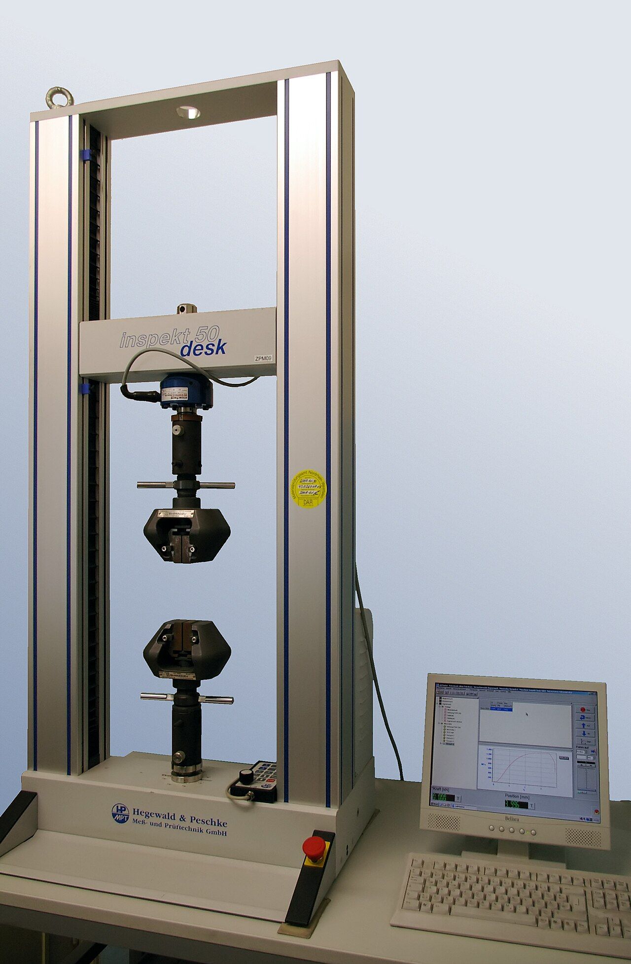
Minimum breaking strength - also written MBL, minimum breaking load - is the lowest force at which the product is verified not to fail when pulled to destruction in a laboratory. It is a floor rather than an average: a well-controlled lot typically breaks above the marked figure. Because it is established by breaking parts, the samples tested are destroyed and never shipped. MBS describes a design and a production process, not the individual part in a buyer’s hand. It is also meaningless without its test geometry: the same connector pulled along its spine, across its width, or with the gate open gives three different numbers.
What is working load limit (WLL), and how does it derive from MBS?
Working load limit, sometimes called safe working load (SWL) or rated load, is the maximum force the manufacturer permits in service, obtained by dividing the minimum breaking strength by a design factor. A shackle with a 100 kN MBS and a 5:1 design factor carries a 20 kN working load limit. MBS is a laboratory result; WLL is a permission for use. A drawing that calls out 25 kN without saying which of the two it means lets the brand and the factory build to figures five times apart.
Why is 5:1 the common safety factor in rigging but not in fall protection?
In lifting and rigging, 5:1 is the usual minimum because the load is known and applied more or less statically. ASME B30.26, the American standard for detachable rigging hardware, requires a minimum design factor of 5 for shackles rated up to and including 150 tons, and the same for eyebolts, turnbuckles, swivel hoist rings, links, rings and swivels.
Personal fall protection cannot work that way: nobody knows in advance how a fall will happen. Instead of a ratio, the standards prescribe minimum hardware strengths and cap the force delivered to the body:
- ANSI/ASSP Z359.12 requires connectors to hold 5,000 lbf (22.2 kN) on the major axis for at least one minute, and 3,600 lbf (16 kN) on the minor axis and on the gate face and gate side.
- EN 362 sets 20 kN on the major axis with the gate closed and locked for most connector classes, 15 kN unlocked, and 7 kN across the minor axis for class B.
- OSHA 1926.502 requires fall arrest anchorages to support at least 5,000 lbf per attached worker, or be designed with a safety factor of at least two under a qualified person.
- The force reaching the worker is capped at the other end: 1,800 lbf (8 kN) under OSHA and Z359, and 6 kN under EN 355 for energy absorbers.
Our separate guide to the ANSI/ASSP Z359 family covers how those documents interlock. The structural point: rigging controls risk with a ratio, fall protection with a floor on hardware strength and a ceiling on human loading.

What do the three kN numbers on a carabiner spine mean?
The three figures printed beside the pictograms rate the connector in three loading conditions:
- Major axis, gate closed, a double-headed arrow along the body. The strongest orientation and the one the product is designed for, typically 20 to 25 kN or higher.
- Minor axis, an arrow across the body. Side-to-side loading across the gate, usually a single-digit or low double-digit figure.
- Gate open, an open-gate pictogram. The spine loaded with the gate unlatched, taking the gate out of the load path, also usually single digits.
Those last two values are lower for a structural reason, not a manufacturing shortcoming. The frame is a slender loop optimised to carry tension along its length; loaded across that loop it bends instead of pulling, and bending resistance in a thin section is a fraction of tensile resistance. With the gate open the frame is effectively a C rather than a closed ring. That is why cross-loading is a real hazard: a connector that rotates until the load runs across the minor axis can sit at a third or less of its marked strength while still looking serviceable. Shape, keeper geometry and gate type all decide how readily that happens.
How is safety hardware tested, and what should a test report show?
Three different activities all get called testing, and they answer different questions:
- Destructive batch testing pulls samples to failure to establish and confirm the MBS, so it runs on samples at type approval and then per defined interval or production lot.
- Proof load testing applies a non-destructive overload - for lifting hardware, commonly twice the working load limit - and confirms the part returns with no permanent deformation or cracking. It verifies workmanship, not ultimate strength.
- 100 percent testing means every unit is proof loaded rather than a sample. It is normal on some critical lifting items and available on request elsewhere, but it adds cost per piece and belongs in the specification rather than an assumption.
A report worth trusting names the part number, revision and lot the samples came from, so the certificate traces to the goods that shipped. It identifies the load cell and its calibration status against a national standard: testing machine force systems are verified to ISO 7500-1, or ASTM E4 in the US. It states axis, fixture, pull rate and hold time, and lists sample size with every individual result rather than a single word reading pass, plus material and heat-treatment records for the same lot.
Static versus dynamic loading: what fall factor changes
A static load is applied slowly and held; a dynamic load arrives with kinetic energy that something must absorb. Fall factor judges how severe that event will be: the distance fallen divided by the length of energy-absorbing element, rope or lanyard, available to catch it. A 2 m fall on 10 m of rope is a factor 0.2 event and feels soft. A 2 m fall on 1 m of lanyard is a factor 2 event, about as harsh as the geometry allows, because the same energy is dissipated over a far shorter stretch.
That is why an energy absorber exists. By tearing stitching in a controlled way, it lengthens the deceleration distance and lowers the peak force. EN 355 requires an energy absorber to hold arrest force at or below 6 kN in the standard drop test while deploying no more than 1.75 m; the US ceiling is 1,800 lbf (8 kN) on a full-body harness. Those limits exist because the human body, not the steel, is the weakest component: a 22 kN connector will transmit a force that would injure the person it protects.
Working with Power Honour
Power Honour has manufactured safety-critical hardware to CE EN, UIAA and ANSI/ASSP Z359 strength requirements for more than 30 years, with forging, investment casting, CNC machining, heat treatment and in-house testing under one ISO 9001 system. If your specification is still moving between MBS and WLL figures, send us the drawing and the target standard, and we will come back with the design factor, test regime and lot-traceability plan we would build to. Drawings and RFQs are welcome at any stage.